

Views: 0 Author: Site Editor Publish Time: 2026-07-26 Origin: Site
Selecting the right passive components determines overall circuit reliability, performance, and product lifespan. Engineers often treat these components as simple ideal elements during early schematic design. Real-world physics quickly complicate this assumption. Choosing the wrong component type leads to premature hardware failure, excessive parasitic losses, thermal runaway, and costly redesign cycles.
Every dielectric material behaves differently under stress. High frequencies expose hidden inductance. High ripple currents generate destructive heat. DC bias strips away effective capacitance in certain materials. To build robust hardware, you must understand these physical limitations. This guide provides a systematic, engineering-focused breakdown of different technologies. We evaluate their dielectrics, performance characteristics, and optimal use cases to guide your technical procurement and design decisions.
Application Dictates Chemistry: No single capacitor fits all needs; selection requires balancing capacitance density against frequency response and stability.
Beware of Hidden Parasitics: Equivalent Series Resistance (ESR) and Equivalent Series Inductance (ESL) often dictate real-world performance in power and high-frequency applications.
Environmental Derating is Mandatory: Temperature, DC bias, and ripple current significantly alter the effective capacitance and lifespan of specific types, particularly ceramics and electrolytics.
Supercapacitor Limitations: While offering massive energy density, supercapacitors require careful voltage balancing and cannot replace standard capacitors in high-frequency AC applications.
Baseline requirements start with matching the required farad value. You must also ensure sufficient voltage headroom to prevent dielectric breakdown. Operating a component at or near its maximum rated voltage accelerates wear and increases failure risk. Engineers typically derate voltage by 20 to 50 percent depending on the dielectric material and operating environment. For example, a 10V rail should ideally use a 16V or 25V rated part to ensure long-term stability.
Tolerance variations differ wildly across manufacturing processes. Precision analog circuits might require tight 1 percent tolerances to maintain accurate filter cutoff frequencies. Bulk power filtering can easily tolerate 20 percent variations without impacting system performance. Understanding these manufacturing variances prevents unexpected behavior in sensitive timing or filtering circuits. Always check the datasheet for tolerance shifts over the component's operational lifespan.
Architectures fall into two main categories: polarized and non-polarized. Polarized types, like electrolytic and tantalum, offer high volumetric efficiency. They pack large farad values into small packages, making them ideal for bulk energy storage. Non-polarized types, such as ceramic and film, allow AC signals to pass in either direction without damage.
Applying reverse voltage to a polarized dielectric causes catastrophic failure. The insulating oxide layer breaks down rapidly. This leads to a massive short circuit, extreme heat generation, and often physical rupture. You must strictly avoid polarized components in pure AC environments or bilateral DC circuits. Even transient reverse voltages can permanently degrade the dielectric layer.
Real components contain hidden parasitic elements. Equivalent Series Resistance (ESR) represents the internal resistance of the leads, plates, and dielectric. In power supply circuits, high ESR combined with high ripple current creates significant I²R power loss. This generates internal heat and degrades efficiency. Low ESR is mandatory for modern switching regulators to maintain tight output voltage regulation.
Equivalent Series Inductance (ESL) limits high-frequency performance. Every physical lead and internal structure adds tiny amounts of inductance. As frequency increases, this inductance blocks current flow. High ESL renders a component useless for high-frequency decoupling applications, failing to suppress fast transient voltage spikes. Surface-mount packages generally exhibit much lower ESL than through-hole equivalents.
Component Type | Typical ESR Range | Typical ESL Range | Best Frequency Range |
|---|---|---|---|
Ceramic (SMD) | 1 mΩ - 50 mΩ | 0.1 nH - 1 nH | 1 MHz - 10 GHz |
Film (Through-Hole) | 10 mΩ - 100 mΩ | 10 nH - 20 nH | 10 kHz - 1 MHz |
Aluminum Electrolytic | 100 mΩ - 2 Ω | 10 nH - 30 nH | 10 Hz - 100 kHz |
Solid Polymer | 5 mΩ - 50 mΩ | 1 nH - 5 nH | 100 kHz - 1 MHz |
Power electronics subject components to continuous charging and discharging cycles. This alternating flow is known as ripple current. High ripple currents induce I²R self-heating due to the internal ESR. If the component cannot dissipate this heat faster than it generates it, thermal runaway occurs. You must calculate the RMS ripple current in your circuit and compare it against the manufacturer's maximum rating.
Thermal rise directly degrades dielectric materials. It accelerates wear-out mechanisms, particularly in wet chemistries where electrolytes evaporate faster at higher temperatures. You must calculate expected power dissipation and verify it against the manufacturer's maximum ripple current ratings. Proper PCB layout, including large copper pours, helps dissipate this internal heat.
Temperature coefficients define how capacitance shifts under thermal stress. Some materials remain incredibly stable across wide temperature ranges. Others lose a massive percentage of their nominal value when exposed to extreme cold or heat. You must account for these shifts in circuits requiring precise timing or frequency control. A filter designed at room temperature might drift out of specification at 85°C.
Dielectric absorption acts like a memory effect. After a complete discharge, the component slowly regains a small voltage. The dielectric material traps charge carriers and releases them over time. This phenomenon severely degrades the accuracy of precision analog circuits like sample-and-hold amplifiers or high-resolution ADCs. Film types generally exhibit the lowest dielectric absorption.
Ceramic technologies dominate modern printed circuit boards. Class 1 dielectrics, like NP0 or C0G, provide high stability and extremely low loss. They do not shift value with temperature changes or applied voltage. However, they offer very low volumetric efficiency. You use Class 1 for precision timing, RF matching, and active filter circuits.
Class 2 dielectrics, such as X7R or Y5V, prioritize high volumetric efficiency. They pack significantly more capacitance into tiny surface-mount packages. The trade-off involves poor temperature stability and significant performance degradation under applied voltage. X7R provides a reasonable middle ground, while Y5V should be avoided in any circuit requiring stable capacitance.
These components excel in high-frequency environments. Engineers deploy them heavily in RF circuits for impedance matching and filtering. They serve as the primary choice for high-frequency bypassing and EMI filtering. Their low ESL allows them to shunt high-frequency noise directly to the ground plane.
Consumer electronics rely on them for stable operation. Computers, communication systems, and high-speed digital buses use hundreds of tiny surface-mount ceramics to decouple power planes and suppress transient noise generated by fast-switching microprocessors. Placing a 0.1µF ceramic directly next to an IC power pin is a standard industry practice.
The DC bias effect represents the most significant risk for Class 2 ceramics. When you apply a DC voltage across the component, the effective capacitance drops dramatically. A 10µF component rated for 10V might only provide 3µF when operating at 5V. You must check manufacturer datasheets for DC bias curves to ensure you have enough capacitance under actual operating conditions.
Mechanical vulnerabilities also pose major risks. Ceramics exhibit the piezoelectric effect, acting like tiny microphones. Mechanical vibration translates into electrical noise (microphonics). Furthermore, rigid ceramic bodies are highly susceptible to flex cracking on PCBs. Board bending during assembly or thermal cycling can fracture the component, leading to latent short circuits.
Orient components parallel to the PCB break-away tabs to reduce bending stress.
Use soft-termination variants that absorb mechanical flex.
Keep large ceramic packages away from mounting holes and board edges.
Implement strict temperature profiling during reflow soldering to prevent thermal shock.
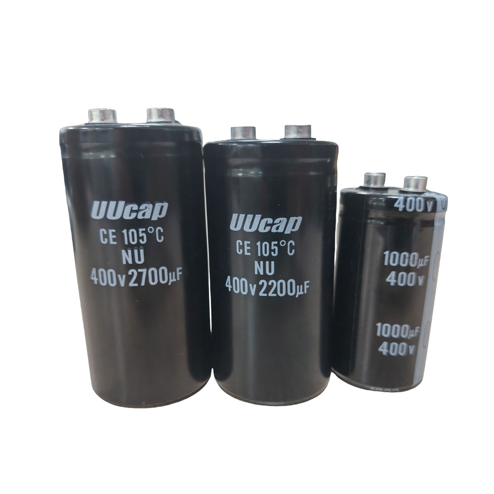
Traditional wet aluminum electrolytics provide cost-effective, high-capacity energy storage. They use a liquid electrolyte to achieve massive farad values. However, they suffer from higher ESR and a finite lifespan due to electrolyte evaporation. Selecting a high-quality Capacitor for industrial applications often involves evaluating these wet types against newer technologies to ensure adequate hold-up time during power interruptions.
Solid polymer variants replace the liquid with a conductive polymer. This drastically lowers the ESR and eliminates the dry-out risk. Solid polymers offer significantly longer lifespans and handle higher ripple currents. They cost more but provide superior reliability in demanding power delivery networks, especially on computer motherboards and server power supplies.
Tantalum technology offers superior volumetric efficiency compared to aluminum types. They maintain highly stable capacitance over time and temperature variations. Engineers specify tantalums for space-constrained layouts where high capacitance is mandatory but physical real estate is limited. They are common in mobile devices and compact medical equipment.
They exhibit lower ESR than standard wet aluminum types. This makes them excellent for filtering in low-voltage DC-DC converters. Their solid construction resists physical shock and vibration better than large aluminum cans. However, they require careful voltage derating to ensure safe operation.
Electrolytics dominate power electronics. They provide bulk power supply smoothing after AC rectification. They store the massive energy required for motor starters and industrial drives. DC-DC converters rely on them to stabilize output voltages under heavy load transients, preventing voltage droop when a processor wakes from sleep mode.
Audio equipment uses specific grades for signal coupling. They block DC bias while allowing low-frequency audio signals to pass between amplifier stages. High-end audio designs often utilize specialized electrolytic formulations to minimize signal distortion and maintain a flat frequency response across the audible spectrum.
Polarization requirements demand strict design discipline. Reverse voltage causes catastrophic failure, often resulting in physical venting or explosion. You must ensure correct orientation during PCB assembly and verify that circuit transients never push the voltage negative. Most aluminum cans feature a scored vent on top to release pressure safely during a failure.
Tantalum types carry specific ignition and thermal runaway risks. A microscopic flaw in the dielectric can cause a localized short. If sufficient current is available, the tantalum ignites. You must strictly derate tantalum voltage by at least 50 percent and limit available inrush current. Modern polymer tantalums mitigate this ignition risk significantly.
Wet aluminum types face a predictable wear-out mechanism. The liquid electrolyte slowly evaporates over time, especially at elevated temperatures. As the electrolyte vanishes, ESR climbs rapidly, and capacitance drops. This eventually causes the power supply to fail or oscillate out of control. You must calculate the expected lifespan based on the actual operating temperature.
Film technologies utilize thin plastic sheets as the dielectric. Polyester (PET) versions offer a smaller footprint and serve well in general-purpose applications. They handle moderate temperatures and provide good insulation resistance. You often find PET films in basic timer circuits and low-frequency analog filters.
Polypropylene (PP) versions deliver extremely low loss and high precision. They exhibit near-zero dielectric absorption and handle high AC voltages effortlessly. PP remains the superior choice for high-frequency, high-power applications where heat generation must remain minimal. Induction heaters and high-power switching supplies rely heavily on PP films.
Engineers deploy film types in demanding power environments. Snubber circuits in power electronics use them to absorb destructive voltage spikes generated by switching transistors. They handle massive peak currents without degrading. Their low ESR prevents them from overheating during these rapid discharge events.
AC line filtering relies entirely on X and Y safety classifications. These components connect directly across the AC mains to suppress EMI. High-fidelity audio equipment also utilizes PP film types in crossover networks due to their low distortion and linear frequency response. They do not introduce the microphonic noise common in ceramic types.
Metallized film construction provides a unique self-healing property. If a high-voltage transient punctures the dielectric, the localized arc vaporizes the surrounding metallization. This clears the short circuit instantly. The component loses a microscopic amount of capacitance but remains fully functional. This makes them ideal for environments with unpredictable voltage spikes.
The primary drawbacks involve physical size and cost. Film types require significantly more volume per microfarad compared to electrolytics or ceramics. They cost more to manufacture. You only specify film when the application demands high voltage, extreme reliability, or self-healing safety features. Through-hole mounting is still standard for large film components.
A supercapacitor utilizes electric double-layer capacitance and pseudocapacitance to store energy. Instead of a conventional solid dielectric, it uses a porous carbon electrode immersed in an electrolyte. This creates a massive surface area. The charge separates at the boundary between the electrode and the electrolyte, achieving massive farad values previously impossible with standard dielectrics.
This architecture bridges the gap between traditional electrostatic storage and electrochemical batteries. They charge and discharge rapidly, unlike chemical batteries. They endure hundreds of thousands of cycles without significant degradation. This makes them perfect for applications requiring frequent, rapid bursts of energy.
These components excel in power backup and peak delivery. Real-time clock (RTC) memory backup uses them to maintain timekeeping during main power loss. They replace coin cell batteries, eliminating chemical leaks and replacement maintenance. A small 1F component can keep an RTC running for weeks.
Regenerative braking systems in industrial robotics capture kinetic energy and dump it rapidly into supercapacitor banks. IoT devices use them to deliver the sudden peak power required for cellular or LoRa radio transmissions, protecting the primary battery from severe voltage droop. This extends the overall life of the primary chemical battery.
The maximum voltage per cell remains very low, typically around 2.7V. To achieve higher operating voltages, you must stack multiple cells in series. This requires active or passive series balancing circuits to prevent any single cell from exceeding its maximum voltage rating. Overvoltage quickly destroys the electrolyte.
They exhibit high ESR compared to standard types. This limits their use in high-frequency ripple filtering. They cannot replace aluminum electrolytics in switching power supplies. You must also account for self-discharge rates, leakage currents, and temperature-dependent aging, which accelerates rapidly above 65°C. High temperatures cause the internal resistance to climb permanently.
Mechanically or electronically tunable components serve specific niche roles. Trimmer capacitors allow manual adjustment during final factory calibration. Engineers use them to fine-tune oscillator frequencies or match antenna impedances. They consist of overlapping plates adjusted via a small setscrew.
Varactors (varactor diodes) provide electronic tuning. Their capacitance changes based on the applied reverse bias voltage. Modern radio tuning circuits, phase-locked loops, and voltage-controlled oscillators rely heavily on varactors for precise frequency control. They eliminate the need for bulky mechanical tuning dials.
Extreme environments demand specialized dielectrics. Mica and glass types offer unparalleled reliability, high voltage handling, and zero tolerance for failure. They exhibit incredible stability across massive temperature extremes and resist high levels of radiation. They do not suffer from the aging effects seen in ceramics or electrolytics.
Aerospace, military, and high-power RF transmitters utilize these components. They cost significantly more than standard commercial parts. You specify mica or glass only when catastrophic failure is unacceptable and environmental conditions destroy conventional materials. They are often hand-assembled and rigorously tested before shipment.
Predicting lifespan requires rigorous thermal analysis. Operating temperature acts as the primary driver of component degradation. For wet electrolytics, the Arrhenius equation provides a reliable framework: lifespan roughly halves for every 10°C increase in operating temperature. A component rated for 2000 hours at 105°C will last approximately 8000 hours at 85°C.
You must calculate the internal temperature rise caused by ripple current and add it to the ambient environment temperature. Strict thermal derating ensures the hardware survives its intended warranty period. Always consult the manufacturer's specific endurance curves rather than relying on generic rules of thumb. Place heat-sensitive components away from hot power transistors on the PCB.
Procurement teams must balance BOM costs with reliability requirements. Consumer-grade components save money but fail rapidly in harsh industrial or automotive environments. Automotive-grade (AEC-Q200) parts guarantee higher reliability but carry significant cost premiums. You must define the operational environment clearly before selecting a component grade.
Regulatory compliance heavily influences sourcing. RoHS directives restrict hazardous substances like lead. Tantalum sourcing requires strict auditing to avoid conflict minerals. Supply chain volatility frequently impacts specific dielectrics, forcing engineers to design flexible PCB footprints that accommodate multiple component sizes or technologies. Dual-footprint layouts prevent production halts during component shortages.
Prototype critical circuits with multiple dielectric types to measure real-world performance differences.
Utilize SPICE models provided by manufacturers to simulate parasitic effects before committing to a PCB layout.
Consult detailed manufacturer datasheets for thermal derating curves and DC bias characteristics.
Implement active balancing circuits when designing energy storage banks with supercapacitors.
Design flexible PCB footprints to accommodate alternative component sizes during supply chain shortages.
A: Polarized capacitors (electrolytic, tantalum) must operate with a specific DC voltage polarity; reversing the voltage causes catastrophic failure. Non-polarized capacitors (ceramic, film) can handle AC signals and operate regardless of voltage direction.
A: Choose tantalum when you need high capacitance in a very small physical footprint, superior long-term stability, and lower ESR. Avoid them in circuits prone to high inrush currents due to their ignition risks.
A: The DC bias effect is a phenomenon in Class 2 ceramics (like X7R) where the effective capacitance drops significantly as the applied DC voltage approaches the component's maximum rating. A 10µF part might only measure 3µF under load.
A: A supercapacitor stores massive amounts of energy electrostatically, offering much higher capacitance than standard types but lower energy density than chemical batteries. It charges and discharges rapidly and endures millions of cycles without chemical degradation.
A: X and Y capacitors are specialized film types used for AC line filtering. X capacitors connect across the line to suppress differential noise. Y capacitors connect from line to ground to suppress common-mode noise and are designed to fail open for safety.
A: High temperatures accelerate chemical and physical degradation. For wet electrolytic types, every 10°C increase in operating temperature generally cuts the expected operational lifespan in half due to accelerated electrolyte evaporation.
A: Premature failure typically results from applying overvoltage, operating at excessive temperatures, applying reverse polarity to polarized types, or subjecting the component to ripple currents that exceed its maximum thermal dissipation rating.


