

Views: 0 Author: Site Editor Publish Time: 2026-07-23 Origin: Site
Energy buffering serves a fundamental role in modern circuit design. While chemical batteries provide sustained power output over long durations through complex internal reactions, a Capacitor delivers instantaneous, high-velocity power delivery. Miscalculating a circuit's charge and discharge requirements leads to catastrophic component failure, unacceptable voltage ripple, or inefficient power delivery in high-stakes industrial and commercial applications. Engineers cannot afford to guess when managing rapid energy transfers.
Shifting the focus from basic electrostatic physics to practical, decision-stage evaluation criteria is necessary for effective system design. Understanding the precise mechanics of energy accumulation and dissipation guides engineers and procurement teams in selecting the right specifications and form factors for their specific power conditioning needs. Proper component selection prevents thermal overloads and ensures stable voltage regulation across varying load conditions.
Electrostatic Storage: A capacitor stores energy within an electric field generated between two conductive plates separated by a dielectric, allowing for near-instantaneous energy release.
Performance Variables: Effective energy release is dictated by Capacitance (storage volume), Voltage Rating (dielectric strength), and Equivalent Series Resistance (ESR), which impacts thermal loss during discharge.
Physical Construction: Internal geometry—such as wound metal foil and dielectric layers versus stacked structures—directly influences the rate of energy dissipation and total charge capacity.
Application Matching: Selecting the correct capacitor requires aligning the discharge time constant with the application—ranging from microsecond bursts in digital strobes to continuous voltage smoothing in power supplies.
Form Factor Matters: High-power and industrial applications necessitate robust physical connections, making components like a screw terminal capacitor essential for handling high inrush currents and mechanical vibration.
The baseline requirement for any capacitive component is accumulating and holding a specific electrical charge without leakage or dielectric breakdown under operational voltage. Success in circuit design hinges on this reliability. If a component cannot maintain its charge state due to internal flaws or environmental stressors, the entire power delivery network becomes unstable. We see this often in field deployments where underspecified components fail prematurely under load.
Energy storage relies on the accumulation of electric charges on closely spaced, insulated surfaces. When voltage is applied across the terminals, electrons gather on the negative plate while leaving the positive plate. This separation of charge creates a concentrated electric field. The insulating material between these plates prevents the electrons from crossing over directly, forcing the energy to remain suspended in the electrostatic field until the external circuit provides a discharge path.
Internal construction maximizes surface area to optimize charge storage within a compact footprint. Manufacturers achieve this by winding alternating layers of ultra-thin metal foil and dielectric material into tight cylindrical rolls. Other designs utilize stacked multi-layer structures. By increasing the active surface area of the conductive plates and minimizing the distance between them, the component achieves higher capacitance values without requiring an excessively large physical enclosure. You will find this winding technique standard across most high-capacity units.
The specific dielectric material determines the energy density and maximum voltage threshold. Ceramic materials offer excellent high-frequency response but limited bulk capacitance. Electrolytic designs utilize a microscopic oxide layer formed on aluminum or tantalum, providing massive surface area and high energy density suitable for bulk filtering. Film dielectrics utilize specialized plastics that excel in high-voltage, high-current pulse applications due to their exceptional insulation resistance and self-healing properties.
The speed at which energy accumulates and dissipates is governed by mathematical realities, specifically the RC time constant. This metric is the product of the circuit's resistance (R) and the capacitance (C). One time constant represents the time required to charge the component to approximately 63.2% of the applied voltage or discharge it to 36.8% of its initial voltage. Understanding this curve is mandatory for timing circuits, pulse generators, and high-speed digital logic.
Consider the common water tank analogy. The tank's volume represents capacitance, the water pressure represents voltage, and the pipe's diameter represents circuit resistance. Energy release rate is entirely contingent on the circuit resistance and how quickly the instantaneous "tap" opens. A massive tank with a tiny pipe will drain slowly, regardless of its total capacity. Similarly, a high-capacitance component paired with high series resistance will release its energy sluggishly, making it useless for applications requiring microsecond power bursts.
To calculate the exact discharge profile, engineers use the formula V(t) = V0 * e^(-t/RC). This equation allows you to plot the voltage decay over time. In practical terms, a circuit is considered fully discharged after five time constants (5RC). If you are designing a strobe flash, you need a very low R value to ensure the 5RC window fits within your required millisecond burst timeframe.
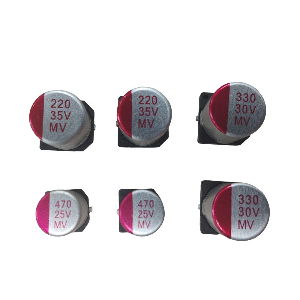
Bridging the gap between theoretical energy storage and real-world performance metrics found on datasheets requires analyzing specific electrical characteristics. Theoretical capacity means little if the component cannot deliver that energy efficiently under operational stress. We evaluate these components based on their ability to survive continuous cycling without degrading.
Internal resistance directly affects the efficiency of energy release. Equivalent Series Resistance (ESR) represents the combined resistance of the dielectric, the internal connections, and the plate materials. When current flows during a rapid discharge, this internal resistance restricts the flow, causing a voltage drop. High ESR limits the peak current output, effectively choking the energy delivery when the circuit demands it most.
High ESR introduces severe thermal implications during rapid discharge cycles. As current pushes through the internal resistance, energy is lost as heat according to the square of the current multiplied by the resistance (I^2R). In high-frequency switching power supplies or heavy-duty motor drives, this continuous heating accelerates electrolyte evaporation and degrades the dielectric. Managing ESR is therefore a thermal management issue as much as an electrical one.
Engineers must measure ESR at the specific operating frequency of their application. A component might show low ESR at 120 Hz but exhibit unacceptably high resistance at 100 kHz. Always consult the frequency multiplier charts provided in the manufacturer's datasheet to determine the actual ESR your circuit will experience.
Engineers constantly evaluate trade-offs between selecting higher capacitance versus higher voltage ratings within a constrained physical footprint. A thicker dielectric increases the voltage rating but decreases the capacitance for a given volume. Conversely, a thinner dielectric boosts capacitance but lowers the threshold for voltage breakdown. Selecting the right balance requires a precise understanding of the application's peak voltage transients and continuous operating parameters.
Safety margins are required to prevent catastrophic failure from voltage spikes. Operating too close to the maximum rated voltage significantly reduces component lifespan. Industry practice dictates derating the voltage specification—often running the component at 50% to 80% of its maximum rating. This buffer ensures that unexpected inductive kickback or grid fluctuations do not puncture the dielectric, which would result in a dead short and potential system destruction.
Dielectric Type | Energy Density | Discharge Speed | Primary Application |
|---|---|---|---|
Aluminum Electrolytic | High | Moderate | Bulk power filtering, DC link |
Ceramic (MLCC) | Low to Medium | Very Fast | High-frequency decoupling |
Polymer Film | Medium | Fast | High-current pulse, safety circuits |
Tantalum | High | Moderate to Fast | Space-constrained filtering |
Categorizing component selection based on the specific energy release profile required by the end product streamlines the engineering process. Different applications demand entirely different discharge characteristics. You cannot swap a bulk filtering unit into a high-frequency pulse circuit and expect it to survive.
Certain use cases require instantaneous, high-voltage energy release. Camera strobes, pulsed lasers, and medical defibrillators depend on the ability to dump massive amounts of stored joules in fractions of a millisecond. These applications cannot tolerate sluggish power delivery; the peak current must reach its maximum value almost instantly to perform the required work.
Ideal dielectric materials for low-inductance, rapid-discharge requirements typically include specialized metallized films. These materials exhibit extremely low ESR and Equivalent Series Inductance (ESL). Low inductance is critical because internal inductance opposes rapid changes in current, acting as a bottleneck during a microsecond pulse. Film dielectrics maintain structural integrity even under the violent mechanical stress induced by massive instantaneous current flows.
In power conversion, components resist changes in voltage over time to provide clean DC power. When AC power is rectified to DC, the resulting waveform contains significant ripple. Large-capacity components absorb excess voltage during the peaks of the ripple and release energy during the troughs. This continuous cycle of micro-charging and discharging smooths the output, delivering the stable DC voltage required by sensitive microprocessors and digital logic.
Bulk capacitance requirements are critical for bridging power interruptions in critical systems. Known as "hold-up time," this is the brief window where the power supply must maintain output voltage after the input power drops out, allowing the system to save data or execute a controlled shutdown. Calculating the required joules for hold-up time dictates the physical size and quantity of the electrolytic components needed on the primary DC bus.
Heavy machinery and HVAC systems introduce high-capacity, high-voltage requirements. Large induction motors draw massive inrush currents when starting, often causing voltage sags on the local grid. Motor start components provide the necessary localized energy burst to overcome the motor's initial mechanical inertia. Power factor correction (PFC) banks neutralize the reactive power generated by inductive loads, improving overall grid efficiency and reducing utility penalties.
Continuous-duty AC applications heavily rely on self-healing film capacitors. In industrial environments, transient voltage spikes frequently exceed the dielectric breakdown threshold. Self-healing technology allows the component to isolate microscopic puncture sites by vaporizing the metallized layer around the fault. This prevents a dead short, allowing the component to continue operating safely with only a negligible loss of total capacitance.
Mechanical and physical integration in high-power environments is just as critical as electrical specifications. A component's ability to survive its operational environment depends heavily on its physical packaging and termination style. We see many failures caused by mechanical fatigue rather than electrical overload.
Standard snap-in or through-hole leads fail under extreme current loads. The thin wire leads or small solder pins lack the cross-sectional area required to carry hundreds of amps. When subjected to massive inrush currents, these standard terminations act like fuses—they heat up rapidly, melt the surrounding solder joints, and ultimately burn out, severing the connection to the circuit board.
Heavy-duty discharge paths demand robust mechanical connections. Specifying a screw terminal capacitor provides superior current-carrying capacity and exceptionally low contact resistance. The thick, threaded aluminum terminals allow for direct bolting of heavy-gauge busbars or ring lugs. This massive metal-to-metal contact area minimizes localized heating at the connection point, ensuring safe and efficient energy transfer during extreme load demands.
Structural advantages become paramount in industrial drives, UPS systems, and renewable energy inverters. These environments subject internal components to constant mechanical vibration and thermal cycling. Standard PCB-mounted components are susceptible to mechanical fatigue; the constant shaking eventually fractures the solder joints or snaps the leads entirely.
A screw terminal design allows the massive aluminum can to be securely clamped directly to the chassis using rigid mounting brackets. This isolates the heavy component from the fragile printed circuit board. By bolting the electrical connections and mechanically securing the housing, engineers eliminate vibration-induced failures, ensuring long-term reliability in harsh industrial deployments.
When installing these heavy-duty components, follow these specific mechanical guidelines:
Verify the torque specifications provided by the manufacturer for the terminal screws to prevent stripping the aluminum threads.
Use appropriate lock washers to maintain clamping force under continuous thermal cycling and vibration.
Mount the component vertically with the terminals facing upward whenever possible to prevent electrolyte leakage through the safety vent.
Ensure the chassis mounting bracket is tightened securely around the center of gravity of the aluminum can.
Understanding what goes wrong post-deployment allows engineers to design robust mitigation strategies. Anticipating failure modes is a fundamental part of power system design. You must account for thermal and lifecycle degradation before finalizing the bill of materials.
Ripple current acts as a primary driver of internal heating. As alternating current rides on top of the DC voltage, it forces the component to constantly charge and discharge. This continuous cycling pushes current through the internal ESR, generating heat from within the core of the winding. If this heat cannot escape faster than it is generated, the internal temperature spirals upward.
Mitigation strategies require aggressive thermal management. Engineers must calculate the expected RMS ripple current and select components rated to handle that specific load. Utilizing active cooling, such as forced air or cold plates, helps extract heat from the aluminum can. Furthermore, selecting components with higher temperature ratings—such as 105°C instead of standard 85°C variants—provides a wider thermal safety margin and significantly extends operational life under heavy ripple loads.
Electrolyte dry-out is an unavoidable reality in aluminum electrolytic designs. Over years of operation, the liquid electrolyte slowly vaporizes and escapes through the rubber end seal. As the electrolyte volume decreases, the ESR rises and the capacitance drops. Eventually, the ESR becomes so high that the component can no longer filter the voltage effectively, leading to system malfunction.
Calculating expected operational life requires analyzing ambient temperature and applied voltage. The industry standard rule of thumb states that component life doubles for every 10°C drop in operating temperature. By designing enclosures with adequate ventilation, keeping components away from heat sinks, and derating the applied voltage, engineers can stretch a rated 2,000-hour lifespan into tens of thousands of hours of reliable field operation.
To ensure your power delivery network remains stable and efficient, follow these next steps:
Calculate your exact energy requirements in Joules and determine the necessary discharge time constant for your specific load.
Evaluate the expected ambient temperatures and RMS ripple currents to select a component with an appropriate thermal rating and ESR profile.
Specify a robust mechanical package, such as a screw terminal capacitor, for applications subject to high inrush currents or mechanical vibration.
Download detailed technical datasheets and use parametric search tools to filter available inventory by precise capacitance and voltage values.
A: The dielectric material determines the permittivity and maximum voltage threshold. Materials with high permittivity allow for greater charge accumulation in a smaller physical volume. The dielectric's insulating strength dictates how much voltage can be applied before breakdown occurs, directly impacting the total energy the component can safely store.
A: Batteries store energy chemically, releasing it slowly over a sustained period through internal reactions. Capacitors store energy electrostatically within an electric field. This allows them to charge and discharge almost instantaneously, providing rapid bursts of power rather than long-term, steady energy delivery.
A: Physical construction dictates internal resistance and inductance. Rolled metal foils provide massive surface area for high capacitance but can introduce higher inductance, slowing discharge slightly. Stacked plate constructions typically offer lower Equivalent Series Inductance (ESL), enabling faster energy release for high-frequency applications.
A: ESR represents the internal resistance of the component. During discharge, high ESR restricts current flow, limiting the speed and peak power of the energy release. Pushing high current through high ESR generates significant internal heat, which degrades the component and shortens its operational lifespan.
A: They are required in high-power industrial applications like motor drives, UPS systems, and heavy-duty power supplies. These environments demand robust mechanical mounting to withstand severe vibration and massive metal terminals to safely conduct high inrush currents without melting standard solder connections.
A: Energy stored is calculated using the formula E = 1/2 * C * V^2, where 'E' is energy in Joules, 'C' is capacitance in Farads, and 'V' is the voltage across the terminals. This demonstrates that energy increases linearly with capacitance but exponentially with voltage.
A: Failure during discharge is typically caused by exceeding the maximum ripple current rating, generating excessive internal heat. It also occurs if the discharge rate exceeds the component's internal limits, leading to dielectric breakdown, mechanical rupture from rapid gas expansion, or terminal failure.


