

Views: 0 Author: Site Editor Publish Time: 2026-07-20 Origin: Site
While a Capacitor is a ubiquitous passive component in hardware design, improper selection remains a leading cause of circuit failure. Hardware engineers constantly battle electromagnetic interference (EMI) and shortened product lifespans due to poor component matching. Matching the correct dielectric, form factor, and performance specifications to specific circuit requirements is a demanding task. You must balance bulk power smoothing needs against high-frequency filtering demands. You also need to manage tight board space and strict bill of materials constraints effectively.
This guide moves beyond basic physics to provide a practical, engineering-focused framework for evaluating applications. We will compare component types and mitigate implementation risks in modern electronic design. By understanding these technical nuances, you can ensure reliable circuit operation under demanding real-world conditions and avoid costly board respins.
Application Dictates Selection: A capacitor’s primary function—whether bulk energy storage, AC coupling, or transient voltage suppression—strictly determines the required dielectric material and specifications.
Hidden Parasitics Matter: Real-world capacitors possess Equivalent Series Resistance (ESR) and Equivalent Series Inductance (ESL), which critically impact high-frequency performance and thermal management.
Form Factor Impacts Reliability: Mounting styles, ranging from micro-SMD to the rugged snap in capacitor, dictate mechanical stability, vibration resistance, and power handling capabilities.
Derating is Mandatory: Reliable circuit design requires strict voltage and temperature derating protocols to prevent premature component degradation and catastrophic failure.
Capacitors act as localized energy reservoirs on the printed circuit board (PCB). They supply sudden current demands to integrated circuits (ICs) during high-speed switching events. When a microprocessor wakes from sleep mode, it pulls a massive transient current. The power supply cannot respond fast enough due to trace inductance. Bulk capacitors step in to deliver this charge instantly, preventing severe voltage droop that would otherwise cause a system reset. In rectifier circuits, they smooth pulsating DC output. They convert raw rectified sine waves into clean, stable DC voltage required by sensitive downstream electronics.
Rapid-discharge applications require energy to release in fractions of a millisecond. Camera photoflashes, pulsed lasers, and medical defibrillators rely on this rapid energy transfer. The component charges slowly over seconds and dumps the entire load instantly. Hold-up time in power supplies is another critical metric. High-capacitance components ensure uninterrupted operation during brief AC mains power interruptions, giving the system enough time to save data and shut down gracefully.
Decoupling, or bypassing, removes high-frequency noise from power rails. It shunts this noise directly to ground before it reaches sensitive microprocessors. You typically place a small ceramic capacitor as close to the IC power pin as physically possible. This maintains signal integrity in digital systems by providing a low-impedance path for high-frequency transients. Without proper decoupling, ground bounce and power rail ringing will corrupt logic levels.
Filtering applications vary widely across analog, audio, and RF circuits. Low-pass filters block high frequencies, allowing only low-frequency signals to pass. High-pass filters do the exact opposite. Band-pass filters allow a specific frequency range to pass while attenuating everything else. Each filter type requires specific capacitance values paired with precise resistors or inductors to achieve the desired cutoff frequency and roll-off characteristics.
Capacitors allow alternating current (AC) signals to pass while simultaneously blocking direct current (DC) bias. This is essential in multi-stage amplifier designs. If you connect two amplifier stages directly, the DC bias from the first stage will saturate the input of the second stage. A coupling capacitor placed between them isolates the DC levels while allowing the AC audio or RF signal to transfer seamlessly.
In audio amplification, DC isolation protects speakers from damaging continuous currents. A DC voltage applied to a speaker voice coil will cause it to overheat and burn out. RF transmission stages also require DC blocking. It ensures component protection and maintains signal integrity across different circuit blocks, preventing unwanted DC offsets from degrading the modulation scheme.
Capacitors work in tandem with resistors to form RC circuits. These networks introduce precise time delays into hardware designs. The RC time constant (Tau = R x C) determines the exact charge and discharge rate. This mechanism is vital in clock generation circuits and simple delay timers. When the voltage across the capacitor reaches a specific threshold, it triggers a comparator or logic gate.
Multivibrators and frequency-determining networks rely heavily on these timing properties. Analog synthesizers use them to establish stable oscillation frequencies for audio generation. RF transmitters use them in phase-locked loops (PLLs) and voltage-controlled oscillators (VCOs). The stability of the dielectric directly impacts the accuracy of the timing circuit over varying temperatures.
Snubber circuits protect mechanical switches and solid-state relays. They absorb the massive inductive kickback generated when a switch opens a circuit containing a motor or transformer. Without a snubber, this flyback voltage causes arcing across the switch contacts, leading to pitting, carbon buildup, and eventual mechanical failure. The capacitor absorbs the transient energy and dissipates it safely through a series resistor.
Transient voltage suppression protects downstream components from external threats. It shields them from electrical overstress (EOS) caused by lightning strikes, electrostatic discharge (ESD), or heavy industrial motor switching. Proper suppression ensures long-term system reliability and prevents catastrophic semiconductor breakdown in field deployments.
Multi-Layer Ceramic Capacitors (MLCCs) excel in high-frequency decoupling, bypassing, and filtering. They dominate modern high-density PCB designs due to their microscopic form factors and extremely low parasitic inductance. Class 1 dielectrics, like C0G or NP0, offer exceptional stability. They have low capacitance limits but exhibit near-zero capacitance shift across extreme temperature ranges. They are mandatory for precision RF and timing circuits.
Class 2 dielectrics, like X7R or X5R, provide massive capacitance in tiny packages. However, they suffer from lower stability and significant voltage derating issues. A 10uF X5R capacitor might lose 60% of its effective capacitance when operated near its rated DC voltage. You must always consult the manufacturer's DC bias curves when designing power rails with Class 2 ceramics.
Aluminum electrolytics provide massive bulk capacitance at a low cost. They are the go-to choice for power supply inputs and low-frequency smoothing on heavy power rails. Their high energy density makes them cost-effective for heavy filtering in motor drives and audio amplifiers. They handle large ripple currents effectively when sized correctly.
However, they have a strictly limited lifespan. The liquid electrolyte inside the aluminum can evaporates over time, especially at high operating temperatures. This evaporation increases the Equivalent Series Resistance (ESR) and decreases the capacitance. Eventually, the increased ESR causes excessive internal heating, leading to component venting or complete open-circuit failure. You must calculate their operational life using the Arrhenius equation.
Tantalum and polymer types suit space-constrained designs requiring high reliability. They offer excellent stability and longevity compared to wet aluminum electrolytics. Polymer capacitors feature extremely low ESR, making them ideal for high-frequency switching regulators. They do not suffer from the severe DC bias degradation seen in Class 2 ceramic types, providing a stable capacitance value under load.
Traditional manganese dioxide tantalums pose severe ignition risks under overvoltage or high surge current conditions. If they fail, they often fail short and can catch fire. Polymer versions mitigate this risk entirely. The conductive polymer does not contain oxygen, offering a much safer alternative for high-reliability aerospace, medical, and enterprise server applications.
Film capacitors dominate high-voltage applications and power electronics. They carry critical safety ratings, designated as X and Y capacitors for AC line filtering. X capacitors connect across the line to filter differential mode noise, while Y capacitors connect from line to ground for common mode noise. They are designed to fail safely without causing a shock hazard.
Precision analog circuits benefit from their incredibly stable characteristics and low dielectric absorption. They feature unique self-healing properties. If a high-voltage transient causes a localized breakdown in the dielectric, the metallized film vaporizes around the fault, clearing the short circuit instantly. They also handle high peak pulse currents exceptionally well, making them ideal for snubber networks.
Supercapacitors bridge the gap between traditional electrostatic types and rechargeable batteries. They excel in high-capacity memory backup, real-time clock (RTC) power, and energy harvesting applications. Short-term power delivery is their primary strength. They can dump massive amounts of current in seconds to start a motor or fire a solenoid.
They offer an incredibly high cycle life compared to lithium-ion batteries, easily surviving hundreds of thousands of charge/discharge cycles without degradation. However, they have very low voltage limits, typically around 2.7V per cell. To achieve higher voltages, you must connect multiple cells in series and implement active or passive balancing circuits to prevent overvoltage on individual cells.
Capacitor Type | Primary Application | Key Advantage | Main Limitation |
|---|---|---|---|
Ceramic (MLCC) | High-frequency decoupling | Compact size, low ESL | DC bias capacitance loss (Class 2) |
Aluminum Electrolytic | Bulk power smoothing | High capacitance density | Limited lifespan (electrolyte dry-out) |
Tantalum Polymer | Space-constrained power | Low ESR, high stability | Lower voltage ratings |
Film | High-voltage safety (X/Y) | Self-healing, high peak current | Large physical size |
Supercapacitor | Memory backup, energy harvesting | Massive cycle life | Low voltage per cell |
SMD packages are essential for automated assembly lines. They allow for rapid pick-and-place manufacturing, drastically reducing production time. SMDs minimize parasitic inductance (ESL) because they lack wire leads. This is critical in high-speed digital circuits where trace inductance can ruin signal integrity. Shorter trace lengths and direct board mounting improve high-frequency response. They enable modern miniaturized electronics, from smartphones to dense server motherboards.
Through-hole mounting remains necessary in specific, demanding scenarios. High-vibration environments, such as automotive engine bays or aerospace applications, demand strong mechanical bonds. Legacy industrial equipment often relies on through-hole components for field repairability. The physical leads provide superior physical anchoring to the PCB. This prevents solder joint fractures under severe mechanical stress or thermal cycling.
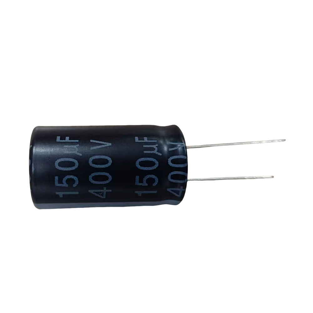
The snap in capacitor features sturdy, specialized leads designed for heavy-duty applications. These leads grip the PCB firmly prior to wave soldering, preventing the bulky component from tilting or falling out during assembly. This form factor is critical in switch-mode power supplies (SMPS), motor drives, and solar inverters. They handle massive ripple currents and possess large physical sizes to dissipate heat. Extreme vibration resistance is mandatory in these heavy-duty power applications, and the snap-in design delivers that mechanical stability.
ESR impacts thermal dissipation directly. It causes I²R losses within the component when ripple current flows through it. This reduces overall efficiency in switching power supplies. High ESR leads to internal heating, which accelerates electrolyte dry-out and causes premature failure. ESL limits effectiveness at high frequencies. It creates an impedance bottleneck, preventing the capacitor from shunting high-frequency noise to ground. You must evaluate both parasitics by reviewing the impedance vs. frequency curves in the datasheet to ensure proper transient response and thermal stability.
Standard engineering practices mandate strict voltage derating. You should operate components at 50% to 80% of their rated voltage. For example, on a 12V power rail, you should use a capacitor rated for at least 25V. This ensures long-term reliability. Voltage spikes from inductive loads or hot-plugging events can easily exceed steady-state conditions. Derating provides a safety margin against these transients. It prevents dielectric breakdown, carbon tracking, and catastrophic short circuits.
Ambient and operational temperatures shift capacitance values significantly. Class 2 ceramics are highly susceptible to this thermal drift. Precision timing, active filters, or RF matching circuits require careful selection. You must choose appropriate temperature coefficients, like C0G or NP0, which maintain their value across the entire industrial temperature range (-40°C to +85°C). Tight tolerance (e.g., 1% or 5%) ensures the circuit operates within designed frequency bands across all environmental conditions, preventing oscillator drift or filter detuning.
You must calculate the expected RMS ripple current accurately using circuit simulation tools. Match this against manufacturer datasheets. Exceeding ripple current ratings causes excessive internal heating. This leads to thermal runaway, pressure buildup, and eventual component venting (the classic popped capacitor). Proper thermal management involves selecting components with adequate physical size and low ESR to dissipate heat safely. You must also consider the ambient temperature inside the enclosure and ensure adequate airflow around bulk capacitors.
Class 2 MLCCs suffer from a severe DC bias effect. They lose a significant percentage of their effective capacitance when a DC voltage is applied across their terminals. A 10uF 0603 package capacitor might only provide 2uF when operated at 5V. You must review manufacturer bias curves during the design phase. Always design based on the effective capacitance in the actual circuit conditions, not the nominal value printed on the reel. Failing to account for this will lead to unstable power supplies and oscillating regulators.
Electrolytic components degrade over time. The Arrhenius equation governs their lifespan calculations. Generally, the lifespan halves for every 10°C increase in operating temperature. If a capacitor is rated for 2000 hours at 105°C, operating it at 95°C extends its life to 4000 hours. You must calculate the expected life based on internal heating (from ripple current) and ambient conditions. Proper cooling, heat sinking, and conservative derating extend operational life significantly, preventing costly field returns.
High AC voltages cause the piezoelectric effect in Class 2 MLCCs. The ceramic material physically expands and contracts with the changing voltage. This vibrates the PCB, turning the board into a speaker and creating a "singing capacitor" issue. This high-pitched whine is unacceptable in consumer electronics. Mitigation strategies include using acoustic noise reduction series (which use thicker bottom terminations), altering the PCB layout to reduce board flex, or switching to tantalum or polymer alternatives, which do not exhibit piezoelectric properties.
Global MLCC shortages frequently disrupt manufacturing schedules. You must design with standard footprints (e.g., 0402, 0603, 0805) rather than odd sizes. Qualify multiple dielectrics and manufacturers during the initial design phase. Ensure your BOM lists at least three acceptable alternatives for every passive component. This mitigates supply chain disruptions and prevents line-down situations. Avoid single-source proprietary packages unless absolutely necessary for extreme performance requirements.
A capacitor is never just a generic energy storage device. Its utility is strictly defined by its dielectric material, hidden parasitics, and physical package. Selecting the wrong component leads to system instability, EMI failures, and field returns.
To shortlist components effectively, follow this sequential decision framework:
Define the circuit function, distinguishing between high-frequency filtering, bulk storage, or precise timing.
Calculate the required capacitance and maximum peak voltage, applying strict 50-80% derating rules.
Select the appropriate dielectric based on ESR, ESL, and temperature stability needs.
Choose the mounting style, utilizing SMD for high-speed signals or a rugged snap-in design for heavy power and vibration resistance.
Next Steps:
Utilize manufacturer SPICE models to simulate in-circuit performance and verify transient response before finalizing the BOM.
Physically test prototypes with thermal imaging cameras to verify component temperatures under maximum ripple current loads.
Rigorously review supplier datasheets for lifecycle data, DC bias characteristics, and impedance curves.
A: It blocks steady DC while acting as a local energy reservoir. It smooths out voltage fluctuations, supplies transient current demands to ICs, and filters out high-frequency noise from the power rails.
A: Calculate the maximum peak voltage the circuit will experience, including transients. Apply a derating factor. Typically, select a component rated for 1.5 to 2 times the maximum expected operating voltage to ensure long-term reliability.
A: Using the wrong dielectric results in severe capacitance loss under DC bias. It causes excessive heat generation due to high ESR, signal distortion in timing circuits, or complete circuit failure from temperature instability.
A: Snap in capacitors are required for bulky, high-capacitance applications like power supply smoothing. These heavy components need mechanical stability on the PCB to prevent tilting before and after wave soldering.
A: Decoupling isolates two parts of a circuit from mutual interference, preventing voltage droop. Bypassing provides a low-impedance path to ground to shunt high-frequency noise away from a specific sensitive component.
A: High ESR causes internal heating when subjected to ripple currents. This degrades power efficiency, accelerates electrolyte evaporation, shortens the component's lifespan, and can eventually lead to thermal failure and venting.
A: Generally no. Supercapacitors bridge the gap for low-power or transient-hold applications. However, standard types discharge energy in fractions of a second, whereas batteries provide sustained energy over long periods through chemical reactions.


