

Views: 0 Author: Site Editor Publish Time: 2026-07-31 Origin: Site
Capacitor failure rarely happens in isolation. On a factory floor or inside a commercial power room, a single blown component acts as the primary catalyst for catastrophic system downtime, industrial power supply failure, and severe hardware damage. When a drive faults out or a power supply goes dark, engineers, maintenance technicians, and procurement teams scramble to restore operations while facing the harsh realities of electrical overstress, thermal degradation, and premature dielectric breakdown. Balancing component specifications against these operational hazards remains a persistent engineering challenge.
Mitigating these failures requires moving far beyond reactive replacement. You must adopt proactive lifecycle management and precise component specification. By implementing strict operational derating and integrating protective enclosures like industrial capacitor boxes/modules, you can drastically enhance system reliability. Understanding the exact root causes of degradation allows your team to deploy robust engineering strategies that extend service life and keep critical infrastructure online.
Thermal and Electrical Stress are Primary Killers: Operating beyond specified voltage, ripple current, amperage, or temperature limits exponentially accelerates dielectric and electrolyte degradation.
Component Selection Dictates Baseline Longevity: The choice between electrolytic, film, and ceramic capacitors fundamentally alters the expected failure mode, vulnerability to environmental stressors, and operational lifespan.
Derating is Non-Negotiable for Reliability: Applying strict voltage, current, and temperature derating protocols is the most effective engineering strategy to extend service life.
System-Level Protection Adds Value: Utilizing integrated capacitor boxes/modules provides necessary environmental shielding, physical protection, thermal management, and scalability for high-demand applications.
Ambient and operational temperatures directly dictate how long a Capacitor will survive in the field. The Arrhenius equation models this relationship, proving that chemical reaction rates increase exponentially with heat. In practical engineering terms, an industry-standard rule of thumb applies: for every 10°C rise above the rated temperature, the expected life of an electrolytic component is halved. Conversely, cooling the component by 10°C doubles its expected lifespan.
Excessive heat vaporizes the internal liquid electrolyte. As the liquid turns to gas, internal pressure builds rapidly inside the aluminum can. If this pressure exceeds the structural limits of the casing and the pressure relief vent fails to open in time, the component will experience a catastrophic rupture. Even if it vents properly, the loss of electrolyte leads to a massive spike in Equivalent Series Resistance (ESR), rendering the component useless.
Operating Temperature | Rated Lifespan (Base: 2000h @ 105°C) | Degradation Status |
|---|---|---|
115°C | 1,000 hours | Accelerated electrolyte vaporization |
105°C | 2,000 hours | Baseline operational wear |
95°C | 4,000 hours | Extended life, stable chemistry |
85°C | 8,000 hours | Optimal thermal conditions |
75°C | 16,000 hours | Maximum longevity achieved |
Electrical overstress (EOS) occurs when a component operates beyond its maximum voltage or current ratings. This leads directly to dielectric breakdown. Continuous exposure to transient voltage spikes punches microscopic holes through the dielectric material. These localized micro-shorts eventually cascade into a complete dead short across the terminals.
High ripple current and over-amperage conditions generate severe internal heating. As alternating current fluctuates through the component, it encounters the natural internal resistance, creating I²R heating. This internal heat compounds the external thermal stress from the ambient environment, accelerating chemical breakdown. High-amperage surges carry enough energy to physically fuse internal connection tabs or melt the internal aluminum foils, causing immediate open circuits and system failure.
All components undergo a natural aging process, but aluminum electrolytic and paper-insulated variants are particularly vulnerable. When an electrolytic component remains unpowered for extended periods on a warehouse shelf, the aluminum oxide dielectric layer degrades. This severely limits its shelf life and makes immediate deployment dangerous.
Internal materials break down physically over time. Liquid electrolytes dry out, paper separators decompose chemically, and aluminum foils corrode. Environmental moisture ingress plays a massive role here. If the rubber bung or epoxy seal at the base of the component becomes compromised, humidity enters the casing. This moisture accelerates foil oxidation and contaminates the electrolyte, dropping the capacitance value and spiking the ESR until the unit fails.
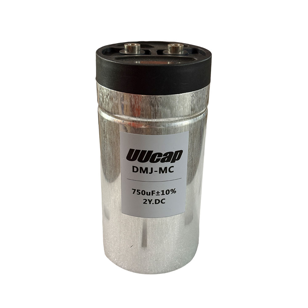
Selecting the right dielectric material dictates how the component will eventually fail. Aluminum electrolytic types offer a massive capacitance-to-volume ratio, making them ideal for bulk filtering. However, they remain highly susceptible to dry-out, thermal degradation, and shelf-life aging. Their typical failure mode involves an open circuit, a gradual loss of capacitance, or catastrophic venting.
Film variants utilize metallized plastic films and possess self-healing properties. When a localized voltage spike punctures the dielectric, the metallized layer vaporizes around the fault, clearing the short circuit. This makes them highly reliable for high-voltage, high-frequency applications. Their failure mode typically manifests as a gradual loss of capacitance rather than a hard short.
Ceramic types, specifically Multi-Layer Ceramic Capacitors (MLCCs), deliver excellent high-frequency response and incredibly low ESR. However, their rigid physical structure makes them vulnerable to mechanical flex cracking on printed circuit boards. They also suffer from thermal shock during soldering. When a ceramic unit cracks, it almost always creates a direct short circuit, which can pull down an entire power rail.
Component Type | Primary Advantage | Primary Vulnerability | Typical Failure Mode |
|---|---|---|---|
Aluminum Electrolytic | High capacitance density | Heat and shelf-life aging | Venting, open circuit, high ESR |
Metallized Film | Self-healing, high voltage | Physical size, cost | Gradual capacitance loss |
Ceramic (MLCC) | Low ESR, high frequency | Mechanical flex cracking | Hard short circuit |
Heavy-duty motor run components and uninterruptible power supply (UPS) units experience exceptionally high failure rates. They endure continuous AC voltage stress and severe harmonic distortion from switching loads. Run component degradation directly impacts electric motors. As the capacitance drops, the motor loses phase shift, causing it to draw more current, overheat, fail to start, and eventually burn out its stator windings.
UPS systems rely on massive DC link banks to smooth out rectified power. These banks face constant ripple current from the inverter stage. The continuous electrical load in these applications demands robust construction to withstand constant thermal cycling and voltage fluctuations. A single weak unit in a series-parallel bank can imbalance the voltage distribution, destroying the entire bank.
Poor manufacturing processes drastically reduce the operational baseline of any component, regardless of the spec sheet. Impure electrolytes, inconsistent foil etching, uneven winding tension, or weak edge seal integrity introduce fatal flaws. Low-quality manufacturing often creates "thin spots" in the dielectric layer. These thin spots act as focal points for early electrical breakdown under load.
Evaluating supplier credibility requires looking past the marketing material. You must review rigorous burn-in testing data, verify adherence to AEC-Q200 or equivalent industrial standards, and ensure transparent material sourcing. High-quality manufacturers use high-purity aluminum and tightly controlled winding machines to ensure uniform dielectric thickness, preventing the localized hot spots that lead to premature failure.
Derating involves the intentional operation of a component well below its maximum rated limits. This practice exponentially increases reliability and safety margins. Engineers should never run a component at 100% of its rated voltage or temperature.
For optimal longevity, recommend derating operational voltage by 20–30%. If your DC bus runs at 400V, specify a 500V or 600V rated unit. Operate at least 15–20°C below the maximum rated temperature threshold. Ripple current derating is equally critical. By keeping the actual ripple current at 70% of the maximum rating, you minimize internal self-heating under heavy load profiles, ensuring the component remains within safe thermal boundaries.
System-level design choices mitigate heat generation and accumulation before it damages components. Strategic PCB placement isolates sensitive units from high-temperature sources like heat sinks, switching transistors, transformers, and power resistors. Integrating active airflow through forced-fan cooling and utilizing thermal potting compounds further dissipates heat away from the component body.
Controlling ambient humidity and preventing exposure to corrosive gases protects the physical integrity of the component. Gases like hydrogen sulfide attack the rubber seals and copper leads, leading to premature terminal corrosion and moisture ingress. Conformal coating on the PCB and sealed enclosures provide the necessary barrier against these environmental threats.
For high-power, industrial, or power factor correction (PFC) applications, discrete components mounted on a board are often insufficient. Structural solutions become necessary. Heavy-duty capacitor boxes/modules provide superior thermal dissipation, often incorporating dedicated aluminum heatsinks or engineered ventilation paths.
These modules offer physical protection against severe environmental contaminants, dust, and moisture. They also provide crucial vibration dampening, preventing mechanical fatigue on the terminal connections. Modular designs allow for safer handling of high-amperage loads, simplify field maintenance, and isolate potential single-component failures from damaging the broader system. When one module degrades, technicians can swap it out quickly without desoldering massive banks of discrete units.
Deploying long-dormant electrolytic components directly into high-voltage systems presents massive safety risks. Unreformed units face rapid leakage current spikes and potential explosion because the aluminum oxide layer has dissolved into the electrolyte during storage. You must rebuild this layer before applying full power.
Reforming requires applying a gradually increasing DC voltage through a current-limiting resistor. This procedure safely rebuilds the dielectric layer before full operational deployment, preventing catastrophic shorting upon startup.
Inspect the component visually for any signs of bulging, leaking, or terminal corrosion.
Connect a high-wattage current-limiting resistor (typically 1kΩ to 10kΩ) in series with the positive terminal.
Connect a variable DC power supply to the circuit.
Slowly increase the voltage in 10% increments, monitoring the voltage drop across the resistor to calculate leakage current.
Hold the voltage at each step until the leakage current drops to a stable, low value.
Once the rated voltage is reached and leakage current is minimal, hold for one hour to fully form the oxide layer.
Safely discharge the component through a bleeder resistor before handling or installing it into the system.
Measurable electrical indicators signal impending failure long before a component vents or shorts. Increasing Equivalent Series Resistance (ESR), decreasing capacitance values, and rising leakage currents serve as the primary warning signs of chemical breakdown.
Integrating routine testing into preventative maintenance schedules helps catch localized hot spots before catastrophic failure occurs. Maintenance teams should utilize specific diagnostic techniques to monitor component health in the field.
Perform routine LCR meter testing during scheduled shutdowns to track capacitance drift over time.
Conduct offline ESR spot checks to identify units that have dried out internally.
Utilize online thermal imaging cameras while the system is under full load to spot components running hotter than their neighbors.
Inspect pressure relief vents visually for slight bulging, which indicates internal gas buildup.
Check terminal connections for torque relaxation and signs of arcing or discoloration.
Audit your current bill of materials to identify any components operating within 10% of their maximum thermal or electrical limits, and replace them with properly derated alternatives.
Evaluate the implementation of robust enclosures and modular banks for high-load systems to improve thermal dissipation and physical protection against environmental contaminants.
Consult with component engineers to establish strict derating protocols tailored to your specific application requirements, focusing heavily on ripple current and ambient temperature.
Implement a preventative maintenance schedule that includes regular ESR testing, capacitance verification, and thermal imaging to detect degradation before it causes system downtime.
A: The combination of thermal stress, high amperage, and electrical overstress leads directly to dielectric breakdown or electrolyte dry-out. Operating beyond specified limits accelerates chemical degradation, causing the majority of field failures.
A: According to the Arrhenius rule, lifespan halves for every 10°C increase above the rated operating temperature. This occurs because heat exponentially accelerates the chemical reactions that degrade the internal electrolyte and dielectric materials.
A: The internal aluminum oxide dielectric layer degrades chemically and dissolves into the electrolyte. The component must be reformed using a current-limiting resistor before use to rebuild this layer and prevent catastrophic shorting upon startup.
A: Look for visual cues like bulging tops, leaking electrolyte, and terminal corrosion. Monitor electrical cues such as rising Equivalent Series Resistance (ESR), dropping capacitance values, and increasing leakage current during routine maintenance.
A: Derating involves intentionally operating a component well below its maximum voltage, current, and temperature limits. This engineering practice exponentially increases reliability, extends service life, and provides necessary safety margins against transient spikes.
A: Use them in high-power, industrial, or power factor correction applications where superior thermal management, environmental protection, physical vibration resistance, and scalable field maintenance are strictly required.
A: Impurities in the aluminum foil, poor winding tolerances, and weak encapsulation create thin spots in the dielectric. These flaws lead to localized dielectric breakdown and thermal runaway under high voltage and current loads.


