

Views: 0 Author: Site Editor Publish Time: 2026-07-28 Origin: Site
A single component failure can trigger catastrophic downtime in multi-million-dollar industrial power systems. When heavy machinery halts, assembly lines freeze, and production schedules collapse, a sub-optimized Capacitor is often the hidden culprit. Engineers face the relentless challenge of balancing strict electrical requirements, harsh environmental realities, and tight budgets without compromising system safety or operational longevity. Selecting the correct component requires moving beyond basic datasheet parameters. Industrial environments subject electronics to extreme thermal cycling, aggressive transient voltage spikes, and relentless mechanical vibration. Relying solely on nominal capacitance and voltage ratings guarantees premature failure in these high-stress deployments. This technical evaluation guide provides a systematic, evidence-based framework for specifying components in heavy-duty applications. By analyzing load requirements, decoding industry test standards, and understanding the physical limitations of different dielectric materials, engineering teams can design robust power systems that withstand the brutal realities of the industrial floor.
Voltage ratings must incorporate substantial safety margins to handle transient spikes and continuous industrial power fluctuations, not just nominal operating voltages.
Equivalent Series Resistance (ESR) is a primary driver of thermal stability; selecting low-ESR components is critical for high-ripple current applications.
Environmental variables (temperature extremes, vibration, humidity) dictate the baseline technology choice, heavily influencing the shift toward robust film technologies over traditional electrolytics.
Strict adherence to voltage and temperature derating protocols is mandatory to achieve the projected operational lifespan in heavy-duty applications.
Compliance with industry-specific test standards (e.g., IEC 61071, UL 810, AEC-Q200) serves as the ultimate benchmark for validating reliability in high-stress deployments.
Successful component selection begins with a rigorous assessment of the application's specific electrical and environmental demands. Engineers must map the continuous load, peak demand, and harmonic distortion levels present in the system. Industrial power grids frequently experience voltage sags, surges, and high-frequency noise generated by adjacent heavy machinery. Understanding these power quality deviations allows designers to specify components capable of absorbing transient energy without exceeding their dielectric breakdown thresholds. You cannot simply look at the nominal voltage; you must evaluate the entire power profile.
Establishing baseline reliability metrics is the next step. Mean Time Between Failures (MTBF) and operational lifespan expectations must align with the equipment's intended duty cycle. A variable frequency drive (VFD) operating 24/7 in a steel mill requires a vastly different reliability profile than a standby generator control panel used intermittently. Engineers must calculate the expected hours of operation and factor in the ambient temperature profile to project realistic end-of-life degradation. We use specific load profiles to determine exactly how much stress the component will endure over a ten-year or twenty-year lifespan.
Decoding regulatory and industry test standards provides a verified benchmark for component durability. Industrial environments demand strict adherence to specialized certifications. IEC 61071 governs power electronic applications, ensuring components can handle severe ripple currents and repetitive peak voltages. UL 810 certification guarantees fail-safe protection mechanisms, preventing catastrophic rupture under fault conditions. For extreme environments, AEC-Q200 qualification provides rigorous stress test validation for temperature cycling, humidity resistance, and mechanical shock, making it highly applicable to rugged industrial designs.
To properly evaluate these criteria, engineering teams should follow a structured approach:
Map the complete electrical load profile, including peak transient events and harmonic frequencies.
Define the required operational lifespan in hours, factoring in the specific duty cycle of the machinery.
Identify all mandatory safety and performance certifications required for the deployment region and industry.
Establish the maximum allowable physical footprint and cooling capacity within the enclosure.
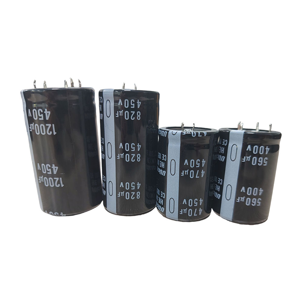
Aluminum electrolytic technology remains a staple for bulk energy storage, low-frequency filtering, and applications requiring massive capacitance in a relatively compact footprint. They are frequently deployed in the DC link of lower-power motor drives and standard power supplies. However, their internal liquid electrolyte presents severe limitations in harsh environments. Over time, high temperatures and internal heating cause the electrolyte to vaporize and dry out, leading to a rapid increase in Equivalent Series Resistance (ESR) and a corresponding drop in capacitance. This wear-out mechanism makes them highly sensitive to temperature extremes and limits their operational lifespan compared to solid-state alternatives.
When specifying electrolytics, you must pay close attention to the ripple current rating and the core temperature. If you push too much ripple current through an electrolytic, the internal heating will accelerate the dry-out process exponentially. We often see field failures where designers failed to account for the ambient temperature inside a sealed enclosure, leading to premature venting and failure of the electrolytic bank.
The structural advantages of metallized film technology have made the DC-Link film capacitor the preferred choice for high-power industrial inverters, motor drives, and renewable energy converters. These components utilize a thin plastic film dielectric, offering exceptionally low ESR, massive ripple current capability, and high voltage tolerance. A defining feature is their self-healing property; localized dielectric breakdowns vaporize the surrounding metallization, clearing the fault and preventing catastrophic short circuits.
Advanced designs utilize segment-patterned metallization, which isolates fault areas like microscopic fuses, ensuring controlled degradation and predictable end-of-life behavior rather than sudden failure. This segmented approach is a massive advantage in high-reliability industrial systems where sudden shorts can destroy expensive IGBT modules or cause dangerous arc flashes.
Heavy-duty HVAC systems, pumps, and compressors rely on distinct designs for motor-run and motor-start functions. Motor-run components are engineered for continuous duty, maintaining phase shifts for optimal motor efficiency. Motor-start variants are designed for short, high-current bursts to overcome initial mechanical inertia and must be disconnected from the circuit immediately after startup. Safety is paramount in these applications.
Standard IEC 60252-1 classifies safety levels (S0, S1, S2, and S3), with S2 and S3 indicating the presence of an internal overpressure disconnector. This mechanical fail-safe severs the internal connection if the component expands due to gas buildup, preventing explosions. We always specify S2 or S3 rated components for any motor-run application located in a hazardous or enclosed environment.
Safety Class (IEC 60252-1) | Protection Type | Failure Mode | Recommended Application |
|---|---|---|---|
S0 | No specific protection | May fail short or open; risk of fire/rupture | Low-power, non-critical open environments |
S1 | Self-healing only | Fails open or short; reduced risk of fire | General industrial motors with external protection |
S2 | Overpressure disconnector | Fails open safely under fault conditions | Heavy-duty HVAC, enclosed pumps, critical drives |
S3 | Segmented film + disconnector | Controlled capacitance loss, fails open safely | High-reliability continuous process machinery |
Multi-Layer Ceramic Capacitors (MLCCs) dominate high-frequency decoupling, noise suppression, and compact control circuit designs. Their low parasitic inductance makes them ideal for filtering fast switching transients. However, industrial engineers must navigate specific risks when deploying MLCCs. The rigid ceramic body is highly susceptible to mechanical cracking under Printed Circuit Board (PCB) flexure or severe vibration. Furthermore, Class II dielectrics (like X7R) exhibit significant DC bias capacitance loss, where the effective capacitance drops drastically as the applied DC voltage approaches the rated voltage.
Tantalum and polymer technologies offer exceptional volumetric efficiency and stable capacitance across wide temperature ranges, making them suitable for space-constrained industrial control boards and sensor interfaces. Unlike wet electrolytics, solid polymer types do not suffer from dry-out, offering lower ESR and longer lifespans. However, traditional manganese dioxide tantalum components pose a severe ignition risk under fault conditions or high-current surges. Strict voltage derating is mandatory to prevent violent thermal runaway and combustion in industrial environments.
Calculating the required capacitance involves analyzing the specific energy storage, hold-up time, or ripple filtering needs of the circuit. Engineers must account for the inevitable degradation of capacitance over time, switching frequency, and temperature. A component specified with a tight initial tolerance may drift significantly out of spec after 10,000 hours of operation at 85°C. To ensure end-of-life performance, designs must incorporate tolerance margins that accommodate this drift, specifying initial values higher than the absolute minimum required by the control loop or power stage.
When calculating hold-up time for an industrial power supply, you must use the end-of-life capacitance value, not the nominal datasheet value. If your system requires 1000uF to maintain regulation during a 20ms line dropout, and you expect a 20% capacitance drop over the equipment's lifespan, you must specify a component with at least 1250uF initial capacitance.
Industrial power systems are plagued by inductive kickback, regenerative braking energy, and grid fluctuations. Differentiating between rated DC voltage, AC voltage, and surge voltage capabilities is critical. The rated continuous voltage must comfortably exceed the maximum steady-state bus voltage. Furthermore, the component must possess a surge voltage rating capable of absorbing repetitive high-energy transients without puncturing the dielectric. Selecting voltage ratings with a 20% to 30% safety margin above the worst-case peak voltage is standard practice to ensure long-term dielectric integrity.
Equivalent Series Resistance (ESR) directly dictates the internal heat generated by the component. The correlation is defined by the power loss formula ($I^2R$). High ripple currents flowing through a high-ESR component generate excessive internal temperatures, accelerating degradation and risking thermal runaway. Engineers must meticulously match the ripple current rating to the application's worst-case switching frequencies and load profiles. Beyond thermals, ESR and capacitance stability directly impact the phase margin and transient response of power supply feedback control loops. Unstable ESR over temperature variations can push a stable control loop into oscillation.
Technology | Typical ESR Range | Ripple Current Capability | Thermal Stability |
|---|---|---|---|
Aluminum Electrolytic | Moderate to High | Low to Moderate | Poor (Highly temperature dependent) |
DC-Link Film | Very Low | Very High | Excellent (Stable across wide range) |
Ceramic (MLCC) | Extremely Low | High (Frequency dependent) | Moderate (Dielectric dependent) |
Polymer | Low | High | Good (Stable over temperature) |
Ambient temperature and internal self-heating combine to form the core operating temperature of the component. This combined thermal stress is the primary accelerator of chemical and physical degradation. Engineers must analyze the thermal resistance of the component and the cooling capacity of the enclosure. Selecting components with upper temperature ratings (e.g., 105°C or 125°C) that significantly exceed the internal enclosure temperatures provides a crucial thermal buffer, exponentially extending the operational lifespan and maintaining parameter stability under heavy loads.
Motor-mounted drives, mining equipment, and heavy industrial machinery subject internal electronics to relentless mechanical stress. High-amplitude vibration attacks capacitor leads, internal winding elements, and PCB solder joints. Standard components will quickly suffer from fatigue-induced lead shear or internal structural collapse. Applications in these environments require anti-vibration mounting configurations, ruggedized plastic or metal casing, and heavy-duty stud mounting options. Compliance with MIL-STD-202 vibration testing methods verifies that the internal construction and external terminals can survive continuous industrial shock profiles.
Moisture ingress is a silent killer of high-voltage electronics. In damp, corrosive, or outdoor industrial environments, humidity penetrates standard plastic enclosures, leading to electrochemical migration, accelerated insulation resistance degradation, and eventual internal short circuits. Engineers must evaluate the necessity for epoxy-sealed, hermetically sealed, or conformal-coated components. Temperature-Humidity-Bias (THB) testing provides a reliable metric for a component's ability to withstand prolonged exposure to high humidity while under electrical stress, ensuring reliability in offshore, agricultural, or unconditioned factory environments.
High-altitude deployments introduce unique physical challenges. As altitude increases, atmospheric pressure drops, reducing the dielectric strength of the surrounding air. This physical reality degrades the cooling efficiency of forced-air systems and compromises the creepage and clearance distances required for high-voltage isolation. Unsealed components may experience internal pressure differentials, leading to casing deformation or seal rupture. Engineers must apply altitude derating factors to both voltage isolation ratings and thermal dissipation models when designing equipment for high-elevation mining or mountainous infrastructure projects.
The relentless push for equipment miniaturization frequently conflicts with the physical volume required for effective heat dissipation and high-voltage isolation. Densely packing high-power components restricts airflow, trapping heat and elevating the localized ambient temperature. Engineers must optimize PCB real estate and enclosure layouts without compromising thermal management. Selecting components with higher volumetric efficiency might save space, but if those components possess higher thermal resistance or lower ripple current capabilities, the resulting heat generation will require larger, more expensive active cooling solutions, negating the initial space savings.
Operating electronic components at their absolute maximum ratings guarantees a short lifespan. Industry-standard derating guidelines dictate operating components at 50% to 80% of their rated voltage and maintaining core temperatures well below their maximum thermal limits. This deliberate reduction in applied stress exponentially increases reliability. Derating mitigates the impact of unexpected transient spikes and provides a buffer against localized thermal hotspots, ensuring the component survives the entire projected lifespan of the industrial equipment.
To implement an effective derating strategy, follow these steps:
Determine the maximum steady-state operating voltage of the circuit under worst-case line conditions.
Select a component with a rated voltage at least 25% to 50% higher than the maximum steady-state voltage.
Calculate the maximum internal hotspot temperature based on ambient conditions and ripple current heating.
Ensure the calculated hotspot temperature remains at least 15°C to 20°C below the component's maximum rated temperature.
System startup and line disturbances often generate uncontrolled inrush currents and high $dV/dt$ transients. These sudden energy surges can exceed the component's peak current handling capability, causing internal metallization vaporization or immediate thermal runaway. Mitigation strategies are essential for robust design. Implementing active pre-charge circuits, utilizing NTC thermistors, and specifically selecting components with robust pulse-current ($I_{peak}$) ratings protect the energy storage bank during power-up sequences and grid fault recoveries.
The industrial supply chain is vulnerable to counterfeit components that misrepresent ESR, voltage ratings, or critical safety class listings. Installing a counterfeit component in a high-power industrial drive introduces severe fire and safety risks. Engineering and procurement teams must establish strict protocols, sourcing exclusively through franchised distributors or directly from original manufacturers. Requiring manufacturer-traceable certificates of conformance (CoC) and reviewing detailed reliability test data ensures the physical components match the rigorous specifications demanded by the design.
Choosing the right energy storage and filtering components requires a holistic evaluation of electrical demands, thermal realities, and mechanical stresses. Simply matching a capacitance value on a schematic ignores the harsh realities of the industrial environment. Prioritize voltage safety margins, thermal stability, and compliance standards above volumetric footprint.
Model thermal and electrical stresses using advanced simulation software to identify potential hotspots and ripple current bottlenecks early in the design phase.
Request detailed, application-specific reliability data and THB test results directly from manufacturers to validate long-term performance claims.
Implement strict voltage and temperature derating protocols, ensuring components operate well below their maximum thresholds to exponentially extend system lifespan.
Conduct physical prototyping and accelerated life testing under worst-case industrial conditions, including maximum ambient temperature and peak mechanical vibration.
A: Operating below the required voltage rating leads to dielectric breakdown. The internal insulation fails, causing a short circuit, thermal runaway, and potential catastrophic rupture. Always apply a safety margin of at least 20% above the maximum expected peak voltage.
A: Required capacitance depends on the motor's power rating, operating voltage, and frequency. Engineers typically use the formula C = (P * 10^6) / (V^2 * f * 2π), adjusting for specific load characteristics and target power factor correction levels.
A: They offer significantly lower Equivalent Series Resistance (ESR), which minimizes internal heating under high ripple currents. They also feature self-healing properties, handle higher voltage surges, and eliminate the risk of electrolyte dry-out, resulting in a much longer operational lifespan.
A: Acceptable ESR varies by design, but values below 10 milliohms are standard for high-frequency switching. Low ESR prevents excessive I^2R losses, maintains control loop phase margin, and ensures stable transient response during rapid load shifts.
A: Yes. Replacing a 370V component with a 440V rated one is perfectly safe and often recommended. The higher voltage rating provides a larger safety margin against transient spikes without altering the capacitance value or motor performance.
A: S0 offers no specific protection and can fail short or open. S1 features self-healing properties but lacks mechanical disconnects. S2 includes an internal overpressure disconnector that safely severs the connection if the component expands, preventing catastrophic rupture.
A: Standard industrial practice dictates derating voltage by 20% to 50% of the maximum rated value. Operating a component at 50-80% of its specified limit drastically reduces dielectric stress, exponentially increasing reliability and extending overall system lifespan.


